|
1. Environment
It is important that the composition of our carbon-graphite material be compatible with the environment to which it may be subjected. Please provide the details of the environment to our engineering department, so that compatible materials can be recommended. Examples of the environment would be exposure to a chemical medium, inert atmosphere, cryogenic service, vacuum, air under normal environmental condition, a high temperature oxidizing environment, or a high temperature neutral environment.
2. Temperature
Though carbon does increase in strength with an increase in temperature, you must not exceed the maximum operating temperature of the materials. A minimum Rockwell C of 55 is recommended. Longer life will also be obtained if the mating materials is ground and/or polished to a 16 micro-inch finish or better.
3. Mating Materials
Our materials may be run against most materials, with best results when run against the harder surfaces. Ceramics and hard chrome plated surfaces are excellent mating materials. We recommend a minimum Rockwell C of 55 and that the mating material be ground to a 16 micro-inch finish or better.
4. Load
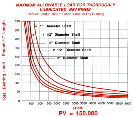
Our materials, in dry running conditions, can withstand a maximum Pressure Velocity (PV) of 15,000. When thoroughly lubricated, the PV may be increased up to 150,000 or more, depending on circumstances. The bearing load, in pounds per square inch, is calculated by figuring the total bearing load divided by the projected area (length x inside diameter) of the bearing. Pressure velocity (PV) is the product of the bushing load x the shaft velocity (in feet per minute). If the calculated PV of a dry running application has approached 15,000, the bushing life can be improved by increasing the bushing length and/or introducing constant and thorough lubrication.
 |
5. Interference Fit
Since Carbon-Graphite bearings are usually installed in metal housings and run against metal shafts, the designer must be aware of the difference in the coefficient of thermal expansion of the materials and take this into consideration when designing the size of the bushing. At maximum operating temperature, the bushing must have at least .0015 inches/inch diameter interference fit.
6. Close-in
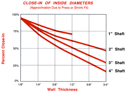
When a carbon-graphite bushing is either pressed into a housing or heat-shrunk into a housing, the inside diameter of the carbon-graphite bearing will shrink in relation to the amount or interference fit on the outside diameter. This shrinkage must be taken into account when designing the inside diameter. Refer to the following chart for approximate values.
 |
7. Running Clearance
The running clearance will vary depending upon the application requirements; however, a general guideline is to have .002 inches/inch of shaft diameter with a minimum of .003" clearance. These clearances apply after the bearing is installed in the housing. With high surface speeds the clearance may be reduced, as for slow surface speeds, the clearance may be increased.
8. Bearing Length
The bearing length should be one to three times the shaft diameter, with one and a half times being the preference.
9. Preferred Design
The preferred design for the bushing is to be a straight sleeve type without shoulders and grooves. Shoulders create stress points and can be a cause of failure. Grooves can be used quite successfully if they are installed with a radius tool bit and do not cut so deep into the wall as to weaken the bearing. The minimum wall thickness of a bushing should be 1/8", with 3/16" preferred. The recommended wall thickness is 1/8" + 10% of the bushing inside diameter.
10. Tolerances
Our bushings can be machined to very close tolerances. The recommended tolerances are listed below; though, much closer tolerances can be machined at an additional cost.
O.D………………. +/-.001"
I.D….…………….. +/-.001"
Length……………..+/-.010"
Concentricity………002"T.I.R.
Surface finish………16 rms of finer
|